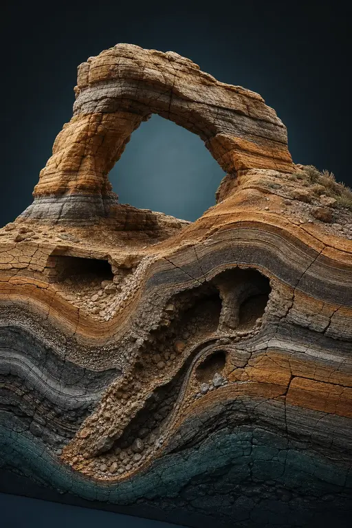
Arches: A Framework for Modeling Complex Terrains
1. Arches: a Framework for Modeling Complex Terrains
A. Peytavie1, E. Galin2, J. Grosjean3, S. Merillou4.
1LIRIS - CNRS - Université Claude Bernard Lyon 1, France
2LIRIS - CNRS - Université Lumière Lyon 2, France
3LSIIT - CNRS - Université Louis Pasteur Strasbourg, France
4XLIM - CNRS - Université de Limoges, France
1.1. Abstract
In this paper, we present a framework for representing complex terrains with such features as overhangs, arches and caves and including different materials such as sand and rocks. Our hybrid model combines a volumetric discrete data structure that stores the different materials and an implicit representation for sculpting and reconstructing the surface of the terrain. Complex scenes can be edited and sculpted interactively with high level tools. We also propose an original rock generation technique that enables us to automatically generate complex rocky sceneries with piles of rocks without any computationally demanding physically-based simulation.
Categories and Subject Descriptors (according to ACM CCS): [Computer Graphics]: Three-Dimensional Graphics and Realism
1.2. 1. Introduction
There are numerous applications that make use of synthetic terrain, and very often the terrain is the dominant visual element in the scene. Such applications include landscape design, flight simulators, battleground simulations, feature film special effects and computer games.
Over the years, graphics researchers have made considerable progress towards developing efficient methods for generating and editing synthetic terrains. There are three main approaches to generating synthetic terrains: fractal landscape modeling, physical erosion simulation and terrain synthesis from images or sample terrain patches.
Existing methods have several limitations. First, they concentrate on large-scale features such as rivers, valleys and mountain ridges, which are usually important visual elements in large-scale terrains. Therefore, they rely on a height field representation and cannot represent overhangs, arches or even caves. Second, they generally do not explicitly model the different materials on the terrain such as sand or rocks: details are added afterwards by a texturing process. Although procedural texturing is often sufficient for generating realistic long-range views, it is necessary to generate the geometric details for closer views. In particular, piles of rocks play an important part in the overall realism of a natural rocky scenery.
In this paper, we present an original approach for author-

Figure 1: Stone arches connecting tunnels and caves.
ing complex terrains with overhangs, arches and caves. Our goal is to propose a compact and efficient model that lends itself for real time editing. Therefore, our goal is not to focus on a physically based modeling system. Instead, we aim at generating physically plausible scenes in real time with physically inspired and phenomenological techniques. More precisely, the main contributions of this paper are as follows:
Hybrid terrain model We introduce a hybrid model that combines a compact volumetric discrete data-structure storing the different materials of the terrain with an implicit representation for efficiently sculpting and reconstructing the surface. Our discrete data structure relies on twodimensional grid of material layers stacks, whereas our implicit surface model is defined as a convolution surface.
Terrain authoring tools We propose a framework that combines some high level terrain modeling and sculpting tools with a simplified physically inspired simulation kernel which automatically stabilizes layers of sand and rocks according to their repose angle. This architecture enables the designer to create complex scenes without the burden of finely editing details by hand.
Procedural generation of rock piles Piles of rocks and pebbles play an important part in the overall realism of a natural rocky scene. We propose a phenomenological approach for simulating rocks detaching from the bedrock and piling together into compact piles. Since stabilizing hundreds of rock pieces would require computationally demanding collision detection and physical simulation, we propose an efficient tiling technique for generating rock piles.
Real time rendering We present a technique for rendering and texturing complex terrains in real time. Our method relies on a real time texturing technique which can be implemented as a GPU shader easily for shading the ground, and on the tiling algorithm for instancing rocks.
The remainder of this paper is organized as follows. In Section 2, we briefly review previous work on terrain modeling. Section 3, presents our hybrid model. We detail high level sculpting and erosion tools in Section 4. Section 5 addresses the automatic generation of piles of rocks. In Section 6, we describe our algorithms for generating the surface mesh and texturing the terrain. Section 7 shows several complex scenes created with our model before we finally conclude our work and propose some future research.
1.3. 2. Related work
There are three main approaches to generating synthetic terrains: fractal landscape modeling, physical erosion simulation and terrain synthesis from images or sample terrain patches.
A variety of stochastic subdivision techniques have been introduced for synthesizing terrains: fractal landscape modeling [Man82], random midpoint displacement techniques [FFC82], square-square subdivision schemes [Mi86]. Szeliski et al. [ST89] addressed the problem of user control by combining deterministic splines and stochastic fractals into constrained fractals. An overview may be found in [EMP*98]. With the recent advances in algorithms and graphics hardware, GPU methods for real-time editing and rendering of procedural terrains have been proposed [SBW06].
Erosion simulation is another approach to synthesizing terrain details based on models of landscape formation and
stream erosion. It is often used as a refinement step after a height field is generated. With appropriately-tuned parameters, these techniques can generate realistic-appearing terrain. Early methods adapted the fractal rules with specific changes to produce eroded terrains [KMN88, PH93]. Physically-based erosion approaches approximate natural terrain formation by simulating the erosion of stream networks. Some material is dissolved and transported by the water flow, and finally deposited at another location. The water movement is determined by local gradient of the terrain in a simple diffusion algorithm [RPP93, Nag98, BF02]. Those methods are based on the simple diffusion model which is not accurate enough to describe the water movement and sediment transportation. Water movement and sediment transportation are closely related to the velocity field of the running water. Therefore fluid simulation methods were integrated into the erosion process by several researchers [CMF98]. Recently, hydraulic erosion simulation techniques have been optimized so as to take full advantage of the high parallel computing power offered by today's graphics processing units [NWD05, MDH07, SBBK08].
Both fractal and physical erosion techniques often involves complex parameter tuning. Image-based alternatives have been proposed [Lew84, PV95] to provide the user with more intuitive control over the synthesized terrain. Recently, an example-based system for terrain synthesis was proposed [ZSTR07], combining patches from samples applied to a user-sketches feature map that specifies where terrain features should occur.
Recent commercial software such as MojoWorld or Terrain 2 are based on fractal synthesis and noise generators and include geological erosion simulation to synthesize realistic-appearing terrain. Control is achieved by changing global parameters in the generation process. Some systems support the user-specified placement of large scale terrain features in the synthesis process.
The very limitation of all those methods is that they rely on a height field representation of the terrain and therefore cannot represent overhangs, arches or even caves. A general technique for generating overhangs was proposed in [GM01]. Overhangs are obtained by a horizontal displacement function to carve the height field. Terrains with overhangs have also been generated with procedural models [GM07]. While procedural terrains can extend over an infinite area or over the entire surface of a planet, they are expensive to render and require topology correction to ensure that the final terrain remains simply connected. Voxel representations have been used to simulate the influence of cracks and joints in the bedrock over the erosion process [IFMC03] and to simulate the geological formation of Goblins [BFO*07]. While those methods can simulate the formation of overhangs, they are computationally demanding and can be effectively used only to model geological features of a limited size.
1.4. 3. Modeling
In this section, we detail our model for representing terrains with overhangs, arches, or caves and with different materials including sand and rocks.
1.4.1. 3.1. Architecture
Terrains are represented by an original hybrid model that combines a discrete volumetric data-structure for storing the different material layers of the terrain and an implicit representation for sculpting and generating the surface of the terrain (Figure 2).

Figure 2: Overview of the architecture of our terrain modeling system.
Editing is performed using either the discrete or the implicit model with a view to using the most adapted representation. The implicit representation is used for sculpting the bedrock and generating the mesh of surface with implicit surface polygonization algorithms, whereas the discrete material layer model is combined with a stabilization simulation kernel which is invoked as a post processing step so as to guarantee that sand and rock layers reach a stable state after every editing step.
1.4.2. 3.2. Material layers
A terrain is defined as a two dimensional grid of material stacks (Figure 3). A material stack is defined as a stack of material layers that are characterized by their thickness and the corresponding material type [BF01]. Our framework currently handles air, water, sand, bedrock, and rocks. Overhangs, arches and caves can be easily created by inserting an air layer between two bedrock layers (Figure 3).
This data-structure is both computationally efficient and less memory demanding than a voxel decomposition of space [JFMC03, BFO*07]. It can store and process complex terrains with many different and complex geological features such as caves (Figure 20), cliffs (Figure 22) and arches (Figure 23) with an effective resolution exceeding (6 billion voxels) with less than 21 megabytes. More statistics can be found in Section 7.

Figure 3: Overview of material layer and material stack data-structures.
For every material , we define a point membership classification function, denoted as , which returns 1 if the material at point is and 0 otherwise. Those functions will be used to define the potential function of the implicit representation.
1.4.3. 3.3. Implicit representation
We define the surface of the different material layers as a convolution surface which smooths the discrete material layer stack. The implicit representation enables us to generate a continuous surface and to create a triangle mesh representation easily with standard implicit surface polygonization techniques [BW97]. Recall that an implicit surface is defined as:
We define the field function as a linear function involving a convolution function [BS91]. Let us first define the convolution function where denotes the skeleton function and refers to the convolution kernel.
For every material , the skeleton function is defined as follows:
Several kernel functions have been proposed, an overview of their properties and the complexity of the evaluation of the integral can be found in [She99]. Kernel functions with an infinite support such as the Gaussian function are computationally demanding as the evaluation of the convolution requires the computation of the integral over the entire terrain. In contrast, kernel functions with a compact support, denoted as , allow a local computation. Several compactly supported kernels have been studied in [She99]. As they are functions of the Euclidean distance to a point, their corresponding compact support is a sphere. Even for skeletons of low dimension such as line segments of triangles, the evaluation of the integral is computationally demanding yielding complex closed form expressions.

Figure 4: Evaluation of the integration domain with kernels with a spherical compact support.
In our case, the skeleton function is a piecewise constant function equal to 1 inside the union of boxes and equal to 0 outside. Thus, the evaluation of the convolution is to be performed over a complex integration domain defined as the intersection of a sphere with the union of boxes (Figure 4), which makes the evaluation of the integral computationally expensive. Therefore, we propose to use the following simple compact support kernel function:
The term denotes the infinite distance function and the parameter refers to the radius of the compact support of the convolution kernel. Since we rely on the infinite distance , the compact support denoted as of the kernel function is a cube of radius (Figure 5). This definition simplifies the computation of the integral to the evaluation of the volume of material inside the compact support of the kernel function (Figure 5). In our system, this evaluation is performed very efficiently by computing the sum of the volume of the boxes of material layers intersecting the kernel support box.

Figure 5: Evaluation of the convolution function: is defined as the volume of material inside the compact support of the kernel function.
Let denote the volume of the cubic compact support , the field function is defined as:
This definition guarantees that if the cubic region around contains only the material , that if does not straddle any layer of this material. if exactly half the volume of is filled with material .
Note that since the potential field function is defined as
a linear function of a convolution performed over piecewise constant functions and , then is a continuous function. Although discontinuities exist in the evaluation of the gradient which determines the normal to the corresponding implicit surface, artifacts are not visible after polygonization.
1.4.4. 3.4. Stabilization simulation
The bedrock layer is always considered as stable, whereas other materials such as sand and rocks should stabilize into successive layers over the bedrock.
Simulating the complex behavior of different granular and continuous materials interacting and blending together is extremely difficult. The angle of repose between two materials is defined as the angle between the horizontal plane and the plane of contact between the two materials when the upper layer is about to slide over the lower. The characterization of the angle of repose of binary granular materials remains a challenging problem. Therefore, we process the different material layer separately.

Figure 6: Layer merging and sorting process.
For all material layers located between two stable bedrock layers, we first merge all the material layers of the same kind (Figure 6). While this prevents us from modeling successive strata of granular materials such as a rock layer between two sediment layers, it greatly simplifies our stabilization algorithm. Then, we sort the material layers above one bedrock layer in the following order: sand, rocks and air. Sorting enables us to use a single angle of repose for every material.

Figure 7: Stabilization of the material layers according to the angle of repose of the different materials.
Eventually, we perform a stabilization simulation step for every material, starting from bottom layers to top layers (Figure 7). Our stabilization simulation is based on the displacement of material from one stack to its neighbors according to the repose angle of every material [MKM89, BF01]. In our implementation, we use 30 – 35 degrees for sand and 40 – 45 degrees for rocks.
Let denote the height of a given rock or sand material stack and , the height of its eight neighbors. We denote the height difference between the central stack and its neighbors by .

Figure 8: Notations for the stabilization algorithm.
Some material moves to a neighboring stack if the angle between the two stacks is greater than the angle of repose . Let denote the size of the side of a material stack. We define if and otherwise. The height of the pile of material to be moved is set as a small constant amount so as to avoid oscillations in the algorithm. The height of material moving from the central stack to a neighboring stack is defined as a weighted average proportional to the height difference:
This process is repeated iteratively until all the material layers are stabilized.
1.5. 4. Editing process
In this section, we present our algorithms for sculpting the bedrock layer and for adding layers of various materials. Our goal is to provide high level tools for authoring complex scenes without the burden of editing details by hand.
We have developed two methods for sculpting the bedrock layer. The first technique consists of locally deforming and carving the terrain in the direction of the normal to the surface. Since directly sculpting the bedrock proves to be a tedious task for editing complex terrain features such as large faults or tunnels, we also developed some specific algorithms for creating cracks or pierce networks of tunnels.
1.5.1. 4.1. Bedrock sculpting
Recall that the bedrock is characterized as an implicit surface . The implicit representation of our terrain enables us to implement implicit sculpting techniques in our framework easily. We have developed a specific tool for displacing

Figure 9: An bumpy overhang sculpted by progressively displacing the bedrock surface along its normal.
the bedrock volume in the direction of its local surface normal.
The sculpting tool is defined by a spherical region of influence with center and radius (Figure 10). The corresponding potential field function is defined as an implicit primitive created from a point skeletal element [WGG99] whose potential field function is defined as , where denotes the Euclidean distance and refers to the potential distribution around the skeleton:

Figure 10: Local displacement of the bedrock surface by updating the corresponding material layers within the editing region.
During the editing process, we project a target vertex onto the bedrock surface. Let denote the potential function prior to editing and the modified field function after the editing process. The overall sculpting process for adding some material to the bedrock surface proceeds as follows:
- 1. Compute the normal to the bedrock surface at the target vertex .
- 2. Create an implicit point primitive with a centered slightly inside the surface of the terrain at where denotes the distance to the surface.
- 3. Compute the modified field function by blending the terrain with the implicit primitive.
- 4. Locally update the bedrock and air material stacks that intersect the region of influence .
5. Finally, stabilize the different material layers.
The parameters and the radius control the extent of material added to the surface. In practice, works well for smoothly sculpting the surface. The algorithm is almost the same for carving the bedrock: the center is located outside of the surface and the field function is modified by using a negative blend .
The material stacks that intersect are subdivided into layers of air or bedrock according to the potential of the modified field function . This is achieved by finding the roots of the equation which represent the upper and lower bounds of the bedrock layers along the central axis of the material stack.
1.5.2. 4.2. Modeling cracks, fractures and tunnels by sweeping
In practice, it is rather impractical to sculpt large canyons, tunnels or cliffs. Sculpting lends itself for editing surface details. Thus, there is a need for generic tools that can generate a variety of terrain features. We propose specific sweeping techniques for modeling such fractures, faults and tunnels.

Figure 11: A deep ravine generated by sweeping a complex profile curve, rocks were created by erosion.
Our method is inspired by the crack generation method proposed in [DGA05]. A template sculpting tool is characterized by a graph representing the branching structure of the paths where the carving tool will be swept and by a set of profile curves that represent the cross sections of the carving tool. The nodes of the graph store the profile curves that define the cross section. The corresponding carving volume is produced by recursively traversing the graph and interpolating the crack profile curves along the arcs of the graph. Profile curves are defined as piecewise cubic spline curves and may define non convex or even more complex cross sections (Figure 12).
Let denote the field function of the terrain. The overall algorithm proceeds as follows:
- 1. Cracks and fractures are created by projecting the graph onto the surface of the terrain so as to create a 3D skeleton . This step can be performed easily with the implicit representation of the terrain.

Figure 12: Fractures carved into the bedrock layer with a non convex carving profile curve.
- 2. Then, we create the profile curves at the vertices of the skeleton by interpolating the profile curves of the crack model and orienting them according to the local normal of the surface of the object and the tangent to the skeleton curve. We define the crack volume by sweeping the interpolating profile curves along the skeleton. We represent the cracking volume as a union of implicit prism primitives using the BlobTree model [WGG99]. The corresponding field function will be denoted as .
- 3. We carve the crack volume out of the terrain by computing the Boolean difference between the terrain and . This step is efficiently performed with the implicit surface representation by defining the modified field function as .
- 4. Eventually, we update and stabilize the modified material stacks (Figure 11).
As for bedrock sculpting, the heights of the modified material stacks are computed by finding the roots of the equation along the central axis of each material stack intersecting the region of modification.
The overall modeling process is the same for caves and tunnels, except that we do not need to project the graph onto the surface. In that case, the graph directly represents the branching structure of the tunnels.
1.5.3. 4.3. Adding granular material
We have developed generic tools for depositing granular materials layers in a complex scene. Our approach is a three dimensional generalization of painting tools that exist for editing height fields.

Figure 13: Adding some sand onto an initial bedrock layer.
Our material depositing tool is defined as a brush characterized by a depositing region and the distribution of material within this region representing the amount of material dropped at any point inside (Figure 13).

Figure 14: Rocks and soil layers (covered with grass) added over a rough initial bedrock layer.
This technique enables us to control the amount and the location of granular material. During the editing process, we invoke the stabilization kernel to stabilize the modified material stacks.
1.5.4. 4.4. Erosion
Existing erosion techniques erode the bedrock layer and produce sediments which are localized in the scene with water transportation simulation. Those methods can be implemented in our framework by adapting the material transportation simulation to non height field terrains. Yet, global erosion methods are difficult to control. Our goal is to propose local erosion tools with controllable parameters. We have developed an original erosion technique for modeling rocks detaching and collapsing into piles onto the ground.

Figure 15: Initial bedrock layer and erosion parameters.
Our approach proceeds in as follows. The designer first defines an erosion tool characterized by the shape of its region of influence, denoted as , and by the way it transforms bedrock into different types of granular materials (Figure 16). In our implementation, bedrock can be eroded either in sand or rocks. Our tool is parameterized by a parameter that defines the relative volume of rocks and sand produced by erosion.
Erosion is performed by sweeping the erosion tool over the surface of the terrain. The region of influence of the erosion tool plays an important part in the realism of the resulting erosion. In nature, erosion can either progressively erode only the surface of the bedrock into sediments, or crack the bedrock along its fragile internal joints into large rock pieces that fall and create a rocky scenery. We have developed two different strategies for simulating those two cases.

Figure 16: Overall erosion process: bedrock transforms into sand and rocks which are transported through the global stabilization process.
When performing a progressive surface erosion, only the bedrock material layers at the surface of the terrain and intersecting the region of erosion are transformed into sand. In contrast, we can simulate rocks detaching from the bedrock and falling apart by computing the bedrock material stacks that intersect the region of erosion , and transforming them into layers of sand and rock according to the parameters and (Figure 16). The stabilization of material layers performs the transport of the eroded materials.
1.6. 5. Modeling rock piles
In this section, we present our method for efficiently generating a set of rocks into contact. Instead of modeling rocks separately and creating piles with physically-based collision detection techniques, we propose to directly generate rock models with contact points. Our method proceeds in three steps. First we generate a cubic tile containing Voronoi cells that can tile the entire space. Second, we create the geometry of rocks by eroding the Voronoi cells. The erosion if performed all over the surface of Voronoi cells but at some random contact points located on the faces so that rocks should nicely pack together. Finally, rock piles are created by instantiating some of the rock models in the cubic tile.
Voronoi cell distribution Let denote a cubic tile. We first generate a Poisson sphere distribution [LD06] with radius and whose centers will be denoted as over the cubic tile . Using a Poisson distribution of radius enables us to control the minimum size of the created Voronoi cells, hence the size of the rocks. We consider that the cube virtually tiles space so as to be able to construct closed Voronoi cells, denoted as for every center . The resulting set of cells periodically tiles space. Creating an aperiodic tiling of Voronoi cells over a set of Corner Cubes using a modified Poisson sphere distribution [LD06] should be possible but needs further investigations beyond the scope of this paper. In practice, we did not observe disturbing repetitive patterns in the rock piles generated with our method.
Generating the rock geometry Rocks are created from the Voronoi cells by performing an erosion simulation step all over the surface of the cells but at some random contact points located on the faces. This method guarantees that rocks should collide and fake a stable arrangement. Recall that our goal is not to perform physically-based simulations but to generate realistic looking models. While we cannot guarantee that the piles are set in a stable configuration, our rock piles are still visually convincing.

Figure 17: Creation of rocks by smoothly eroding the geometry of the Voronoi cells and preserving contact points.
Our method proceeds in two steps (Figure 17). We first create the contact points, denoted as , by generating random points on the faces between the cells and . For every contact point , we define a function denoted as representing the local resistance to erosion with respect to the distance . The resistance should be a smoothly decreasing function of the distance between a point in space and the contact point . Recall that is the Poisson radius, we propose to use the following Gaussian function:
For every Voronoi cell, we generate the corresponding rock geometry by simulating a uniform erosion weighted by the resistance functions (Figure 17). Our erosion simulation is based on the spheroidal erosion technique proposed in [BFO*07]. Note that this process is performed once and for all as a pre-processing step.
Rock instantiation We generate rocks on the ground by analyzing every corner cube straddling a rock material layer. We instantiate rocks whose corresponding Voronoi center lies within a rock material layer (Figure 18). Although rocks on the ground may often intersect the ground mesh, those artifacts are rarely seen.

Figure 18: Rock instantiation process.
In practice, for large rock piles, only the rocks on the top layers are visible and contribute to the final image. Therefore we eliminate rocks whose distance to the surface is larger than twice the maximum radius of Voronoi embedding spheres.

Figure 19: A closeup of rocks piled on the ground.
Our method creates convincing piles of rocks very efficiently by instantiating only a few different mesh models. While we cannot guarantee that the rocks are set in a stable configuration, they are into contact and the resulting arrangements look physically plausible and convincing (Figure 19).
1.7. 6. Rendering
In this section, we present our method for texturing and rendering terrains of arbitrary geometry. Our approach consists in creating only one textured triangle mesh for bedrock and sand - which will be referred to as the ground mesh - whereas rocks are treated separately with the specific instantiation process. The ground mesh is textured by blending different material textures according to the ratio of material layers surfacing the ground.
Ground mesh generation We generate a triangle mesh representing the ground by polygonizing the implicit representation of the terrain. Instead of polygonizing the different material layers independently, we create one implicit surface from the skeleton defined as the union of sand and bedrock. Thus we use the following skeleton function:

Figure 20: Caves connected by a network of tunnels and stone bridges sculpted by sweeping and erosion tools. The rock piles in the tunnels and at the bottom of the huge chasm were added by eroding some parts of the walls.
Standard polygonization techniques [BW97] are used to generate the ground mesh.
Texturing terrains of arbitrary geometry The texture of the different materials can be generated procedurally [EMP*98]. While this method is efficient for off line rendering, it is computationally demanding for real time rendering as generating several procedural textures on the fly and blending them would overload the Graphics Processing Unit. Since we are dealing with terrains of arbitrary topology and geometry, computing the coordinates for texture mapping becomes a challenging problem.
We propose an automatic technique for mapping material textures onto the ground mesh in real time without computing and storing uv-coordinates. Our approach is inspired by [Gei07]. Let denote a vertex of a triangle of the ground mesh, and denote its normal. Let denote the texture color at coordinates and the texture color for vertex . We define the color at vertex by blending the three colors obtained by texture mapping along the main three world axes:
The blending coefficients , and are computed as a function of the normal with a view to blending the contributing textures. Let denote the norm of , we define coefficients as:
The exponent characterizes the smoothness of the blend between axis projected textures. In our implementation, we use . We implemented this texturing technique both as a HLSL shader for real time rendering and as a Mental Ray® shader for producing the high quality images shown through out the paper as well as the accompanying video.
Texture blending The ground mesh is textured according to the type of materials at the surface of the ground. Our approach consists in blending the texture of every different material according to the ratio of neighboring materials.

Figure 21: Evaluation of the amount of visible surface for every different material.
For every vertex of the mesh, we evaluate the ratio of visible materials in a cubic box domain centered at (Figure 21). This is performed very efficiently by computing the visible surface of the material stacks intersecting .
1.8. 7. Results
We have implemented our hybrid terrain model and the modeling tools into a modeling application coded in C++. We have applied our method to create different varieties of complex rocky sceneries with complex geological features including caves (Figure 20), cliffs with overhangs (Figure 22) and arches (Figure 23).
| Terrain | Effective voxel resolution | Memory |
|---|---|---|
| Cave | 21 Mb | |
| Canyon | 14 Mb | |
| Cliff | 26 Mb |
Table 1: Memory statistics for various scenes.
Our material layer data-structure can store non height field terrains very efficiently. Table 1 reports the amount of memory used for modeling different scenes and the effective resolution of the corresponding voxel decomposition of space.

Figure 22: A canyon with rocks detached from the cliffs.
For instance the large cave scene (Figure 20) has been created with an effective resolution exceeding (6 billion voxels) with less than 21 megabytes. Note that the cliff scene with a smaller effective resolution (4 billion voxels) requires more memory because its overall geometry is more complex with many different material layers.
| Terrain | Rocks | Tile | Generating | Instancing |
|---|---|---|---|---|
| Cave | 1941 | 50 | 30.2 | 0.6 |
| Canyon | 6113 | 70 | 44.1 | 0.9 |
| Cliff | 2931 | 50 | 19.0 | 0.4 |
Table 2: Statistics for the rock instantiation.
The triangle meshes representing the cave, the canyon and the arches sceneries have 818 940, 760 769 and 360 698 triangles respectively. The images shown throughout the paper have a resolution.
Our rock pile generation technique can create thousands of rocks piled together very efficiently. Table 2 reports the total number of rocks in different scenes, the number of rocks per tile as well as timings (in seconds) for generating the tiles and performing the instantiation process. Recall that the geometry of rocks in the cubic tile is generated once and for all as a preprocessing step.
Like with all periodic tiling methods, artifacts may appear such as recurring patterns of rocks arranged in the same orientation, or rocks on the ground with an unnatural unsteady position.
1.9. 8. Conclusion
We have presented an original approach for representing complex terrains. Our framework can model overhangs, arches, or caves with granular materials such as sand and rocks. Our hybrid model combines a compact material layer data structure and an implicit representation for sculpting and reconstructing the surface of the terrain. We have proposed several high level tools for authoring complex scenes.
In particular, we presented a very efficient erosion tool as a modeling operator for automatically generating rock and sand piles. Our approach allows the designer to sculpt large complex rocky scenes without computationally demanding physically-based simulation. Our system has been used to successfully construct a vast variety of scenes with original and unique geological features.
In the future, we plan to develop new modeling and simulation tools. We are currently working on combining erosion and ecosystem simulation with a view to creating a unified framework for generating highly detailed and convincing grounds covered with vegetation but also with lichens, mosses, broken branches or fallen leaves. We also plan to investigate the generation of aperiodic rock tiles to improve the overall aspect of rocky sceneries.
1.10. Acknowledgements
This work was supported by Agence Nationale de la Recherche as ANR-06-MDCA-004-01 project. We wish to credit Eden Games and Widescreen Games for their participation to the project. Special thanks go to Pascal Bouvier and Robert Foriel (Widescreen Games) for developing the real time HLSL and Mental Ray shaders, and to Etienne Duranton (LIRIS) for participating to the implementation of the framework.
1.11. References
- [BF01] BENES B., FORSBACH R.: Layered data representation for visual simulation of terrain erosion. In Proceedings of the 17th Spring conference on Computer graphics (2001), pp. 80–85. 3, 5
- [BF02] BENES B., FORSBACH R.: Visual simulation of hydraulic erosion. In Journal of WSCG (2002), vol. 10, pp. 79–86. 2
- [BFO*07] BEARDALL M., FARLEY M., OUDERKIRK D., SMITH J., JONES M., EGBERT P.: Goblins by spheroidal weathering. In Eurographics Workshop on Natural Phenomena (2007), pp. 7–14. 2, 3, 8
- [BS91] BLOOMENTHAL J., SHOEMAKE K.: Convolution surfaces. Computer Graphics 25, 4 (1991), 251–256. 3
- [BW97] BLOOMENTHAL J., WYVILL B.: Introduction to Implicit Surfaces. Morgan Kaufmann, 1997. 3, 9

Figure 23: Arches created by first carving a rough cliff profile into a block of bedrock, and then interactively extruding and sculpting arches. The final weathered appearance was obtained by concentrating erosion on the walls of the cliffs.
- [CMF98] CHIBA N., MURAOKA K., FUJITA K.: An erosion model based on velocity fields for the visual simulation of mountain scenery. Journal of Visualization and Computer Animation 9, 4 (1998), 185–194. 2
- [DGA05] DESBENOIT B., GALIN E., AKKOUCH S.: Modeling cracks and fractures. The Visual Computer 21, 8–10 (2005), 717–726. 6
- [EMP*98] EBERT D., MUSGRAVE K., PEACHEY D., PERLIN K., WORLEY S.: Texturing and Modeling: A Procedural Approach. Academic Press Professional, 1998. 2, 9
- [FFC82] FOURNIER A., FUSSELL D., CARPENTER L.: Computer rendering of stochastic models. Communication of the ACM 25, 6 (1982), 371–384. 2
- [Gei07] GEISS R.: Generating complex procedural terrains using the GPU. In GPU Gems 3 (2007), Addison-Wesley. 9
- [GM01] GAMITO M., MUSGRAVE F. K.: Procedural landscapes with overhangs. In 10th Portuguese Computer Graphics Meeting (2001). 2
- [GM07] GAMITO M. N., MADDOCK S. C.: Ray casting implicit fractal surfaces with reduced affine arithmetic. The Visual Computer 23, 3 (2007), 155–165. 2
- [IFMC03] ITO T., FUJIMOTO T., MURAOKA K., CHIBA N.: Modeling rocky scenery taking into account joints. In Computer Graphics International (2003), pp. 244–247. 2, 3
- [KMN88] KELLEY A., MALIN M., NIELSON G.: Terrain simulation using a model of stream erosion. In Proceedings of SIGGRAPH (1988), pp. 263–268. 2
- [LD06] LAGAE A., DUTRÉ P.: Poisson sphere distributions. In Vision, Modeling, and Visualization (2006), pp. 373–379. 7, 8
- [Lew84] LEWIS J.-P.: Texture synthesis for digital painting. In Proceedings of SIGGRAPH (1984), pp. 245–252. 2
- [Man82] MANDELBROT B.: The Fractal Geometry of Nature. W. H. Freeman, August 1982. 2
- [MDH07] MEI X., DECAUDIN P., HU B.: Fast hydraulic erosion simulation and visualization on GPU. In Pacific Graphics (2007), pp. 47–56. 2
- [Mil86] MILLER G.: The definition and rendering of terrain maps. In Proceedings of SIGGRAPH (1986), pp. 39–48. 2
- [MKM89] MUSGRAVE F. K., KOLB C. E., MACE R. S.: The synthesis and rendering of eroded fractal terrains. In Proceedings of SIGGRAPH (1989), pp. 41–50. 5
- [Nag98] NAGASHIMA K.: Computer generation of eroded valley and mountain terrains. The Visual Computer 13, 9–10 (1998), 456–464. 2
- [NWD05] NEIDHOLD B., WACKER M., DEUSSEN O.: Interactive physically based fluid and erosion simulation. In Eurographics Workshop on Natural Phenomena (2005), pp. 25–32. 2
- [PH93] PRUSINKIEWICZ P., HAMMEL M.: A fractal model of mountains with rivers. In Graphics Interface (1993), pp. 174–180. 2
- [PV95] PERLIN K., VELHO L.: Live paint: painting with procedural multiscale textures. In Proceedings of SIGGRAPH (1995), pp. 153–160. 2
- [RPP93] ROUDIER P., PEROCH B., PERRIN M.: Landscapes synthesis achieved through erosion and deposition process simulation. Computer Graphics Forum 12, 3 (1993), 375–383. 2
- [SBBK08] STAVA O., BENES B., BRISBIN M., KRIVÁNEK J.: Interactive terrain modeling using hydraulic erosion. In ACM SIGGRAPH/Eurographics Symposium on Computer Animation (2008), pp. 201–210. 2
- [SBW06] SCHNEIDER J., BOLDTE T., WESTERMANN R.: Real-time editing, synthesis, and rendering of infinite landscapes on GPUs. In Conference on Vision, Modeling, and Visualization (2006), pp. 153–160. 2
- [She99] SHERSTYUK A.: Kernel functions in convolution surfaces: a comparative analysis. The Visual Computer 15 (1999), 15–4. 3
- [ST89] SZELISKI R., TERZOPOULOS D.: From splines to fractals. In Proceedings of SIGGRAPH (1989), pp. 51–60. 2
- [WGG99] WYVILL B., GUY A., GALIN E.: Extending the csg tree (warping, blending and boolean operations in an implicit surface modeling system). Computer Graphics Forum 18, 2 (1999), 149–158. 5, 6
- [ZSTR07] ZHOU H., SUN J., TURK G., REHG J.: Terrain synthesis from digital elevation models. IEEE Transactions on Visualization and Computer Graphics 13, 4 (2007), 834–848. 2